Creating a Motion Sensor with XMotion V3 Board, MPU6050, and SSD1306 OLED Display
Hello folks! In this post, I’ll walk you through step-by-step instructions on how to integrate an MPU6050 accelerometer and gyroscope sensor with an SSD1306 OLED display using the XMotion V3 board. With this project, you’ll learn how to equip your board with motion detection capabilities.

Step 1: Make the Connections
Firstly, solder female headers onto the SDA, SCL, and power pins of the XMotion V3 board. This step is essential to connect your display and sensor to your board.

Step 2: Connect the Display
Solder the pins of the SSD1306 OLED display to the same pins on the board. This step establishes the interface through which you’ll display the data.


Step 3: Upload the Software
Upload the software to your board using Arduino IDE or any suitable software development tool. In this step, you’ll need to create a program that reads data from the MPU6050 sensor and prints it to the OLED display.

#include <MPU6050_tockn.h>
#include <Wire.h>
#include <U8g2lib.h>
MPU6050 mpu6050(Wire);
U8G2_SSD1306_128X32_UNIVISION_F_HW_I2C u8g2(U8G2_R0, /* reset=*/ U8X8_PIN_NONE); //Connection pins for the OLED display
void setup() {
Serial.begin(9600);
Wire.begin();
mpu6050.begin();
mpu6050.calcGyroOffsets(true);
u8g2.begin(); // Initialize the OLED display
}
void loop() {
mpu6050.update();
// Retrieve angle data
float angleX = mpu6050.getAngleX();
float angleY = mpu6050.getAngleY();
float angleZ = mpu6050.getAngleZ();
u8g2.clearBuffer(); // Clear screen
// Print angle data to the screen
u8g2.setFont(u8g2_font_profont10_mr);
u8g2.setCursor(0, 10);
u8g2.print(“Angle X: “);
u8g2.print(angleX);
u8g2.setCursor(0, 20);
u8g2.print(“Angle Y: “);
u8g2.print(angleY);
u8g2.setCursor(0, 30);
u8g2.print(“Angle Z: “);
u8g2.print(angleZ);
u8g2.sendBuffer(); // Send the buffer to the screen
delay(100);
}
Step 4: Monitor the Data
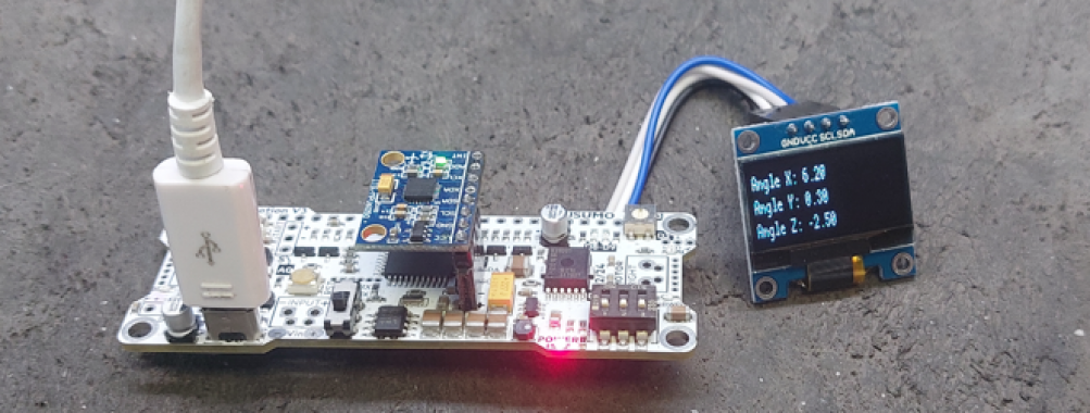
Power up your board and ensure that the data is correctly displayed on the OLED screen. Here, you can monitor the acceleration and gyro data from the MPU6050 sensor.
Once you’ve completed these steps, your XMotion V3 board will be equipped with motion detection capabilities, and you’ll be able to display this data on the SSD1306 OLED screen.
I hope these steps help you create your project and achieve an exciting result!