
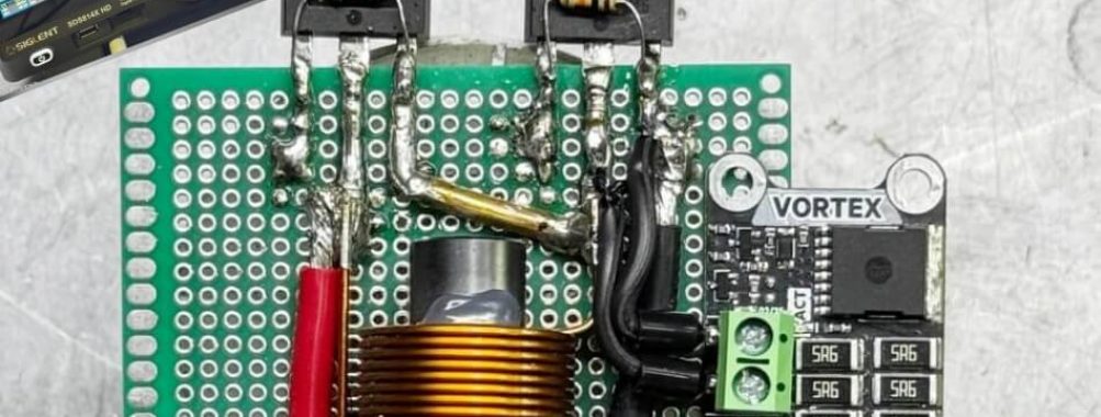
Vortex, Transient Voltage Adsorber/Clamp Demonstration
In that article we will explore new shunt clamp module , “Vortex” , from JSumo. When driving heavy inductive loads like DC motors at high switching frequencies, these sudden voltage spikes can wreak havoc on your power bus and destroy sensitive components.
We usually this problems mostly on high energy output robots. These type robots do more than just draw current, they also generate significant electrical noise and parasitic transients.
To keep your system stable and your motor driver MOSFETs alive, relying solely on passive components such as TVSs, MOVs, Snubbers are often not enough. This is exactly where the VORTEX shunt clamp comes into play.
If we quickly compare:
TVS: Fast but limited duration (Usually under milliseconds)
MOV: Slower and not good for repetetive signals.
Snubber: Can take good energy but slower.
Voltage Clamp: Our solution, Vortex. Bigger active circuit, fast and longer duration to adsorb excessive energy. (Though bigger versions are used in many industries)
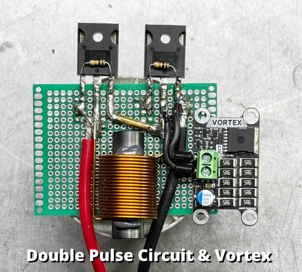
Voltage Clamp Vortex, Hardware
At the core of our hardware protection strategy is the Vortex shunt clamp, an active voltage clamping circuit designed to handle the massive inductive energy that passive components simply cannot survive. While TVS (Transient Voltage Suppressor) diodes are excellent for momentary, microsecond (uS) level ESD spikes, they lack the thermal mass and continuous power dissipation capacity required for the repetitive, high-energy inductive kickbacks generated during continuous PWM motor control. Our module solves this by constantly monitoring the DC bus voltage. The moment this voltage exceeds a predefined safe threshold, an onboard comparator instantly triggers a dedicated switching MOSFET to divert (shunt) the excess current through a heavy-duty resistor bank. Instead of failing under sustained loads like a TVS diode would, this active switching approach effectively caps the bus voltage by converting the destructive regenerative energy into heat, ensuring continuous and robust protection for the entire power stage.
How to integrate to System, Robot, Circuit…?
Easy, we will attach module same as adding bulk capacitor or another module to system or robot. Just attach to the main power supply. Here one important thing to keep in mind. Always Vortex Module’s clamp voltage must be higher than (little more higher) battery voltage. So as board conducts at 27.5V system power MUST be lower than it such as 6S LiPo (25.2V) or 4S LiPo (16.8V) or 3S Lipo (12.6V)
Wiring the vortex module is straightforward and conceptually similar to installing a TVS diode, it is connected in parallel directly across the main DC power bus. However, in high-frequency power electronics, physical placement is just as critical as the schematic itself. To maximize its protective capabilities, the module must be mounted as close as possible to the sensitive control board or device you are safeguarding. So we should use short & thich wires.
More importantly, it should be positioned strategically between the source of the parasitic noise (the inductive load or motor driver stage) and the protected circuitry. Even though the electrical connection is strictly parallel, the physical wiring layout must be routed so that the incoming voltage spikes ‘visit’ the shunt regulator’s terminals first. This strategic interception ensures that the VECTOR can instantly clamp and absorb the destructive transient energy before the spike has any chance to propagate further down the line and reach your vulnerable components.
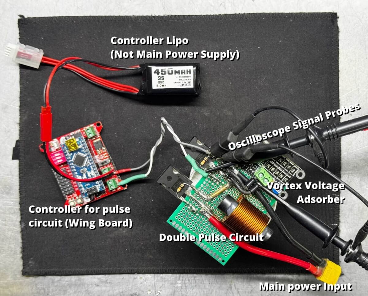
Test Condition
We used two MOSFETs in half brigde mode with the “Leakage” inductance is a coil connected paralel to the high side MOSFET. We used high-side MOSFET’s bodydiode as a flywheel diod. We trigger only low side mosfet to creating inductive load. Trigger signal is 20% duty cycle PWM at 10 kHz. This designs is known/used as double pulse circuit.
In this test we aimed protect the low side MOSFET. We choosed MOSFET IRFP064N which’s Drain-To-Source voltage capability is 55V with 110A current rating ( https://www.infineon.com/assets/row/public/documents/24/49/infineon-irfp064n-datasheet-en.pdf).
To properly stress test the Vortex Module and push its boundaries, we deliberately selected an inductor significantly larger than standard parasitic leakage inductance with fast switching.
Test Results
The results are highly satisfactory. We reached the what we aimed.
Initially, we captured the voltage transients using an oscilloscope, images below:
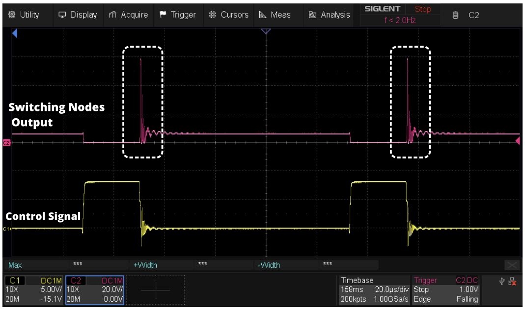
Interpreting the signal above, we see very high and short-lived transient voltages generated by inductive loads (such as DC motors) in the output signal. These voltages are strong enough to affect even the input signal (yellow signal). The voltage difference can reach up to 55V. This means that even if you are operating at a low voltages such as 12V, inductive loads can put an excessive voltage load on your system. This transients can damage circuits easily.
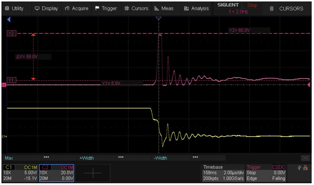
Here you can see a zoomed-in version of an overshoot signal. Our Delta Y difference is 55V.
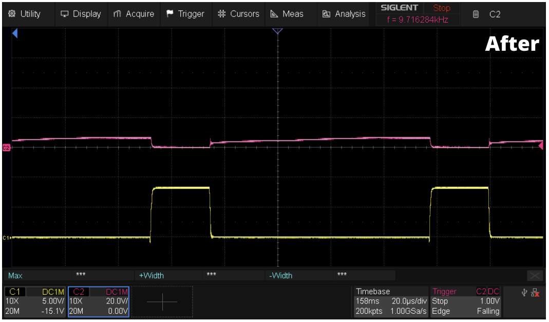
And here, These are the signals that the Vortex circuit compensates when connected in parallel to the system.